Accessibility links Skip to main content

Minimizing Risks on the Sports Field

In light of the recent incidents involving light poles at two hockey clubs in Delft and The Hague, we would like to once again emphasize the importance of preventive safety measures. Over the past few weeks, we have observed that a great deal of confusion and uncertainty has arisen regarding the safety of sports field light poles.

Continue reading
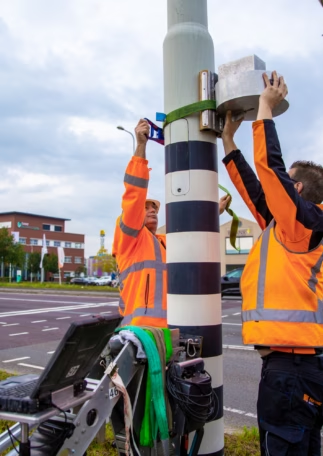
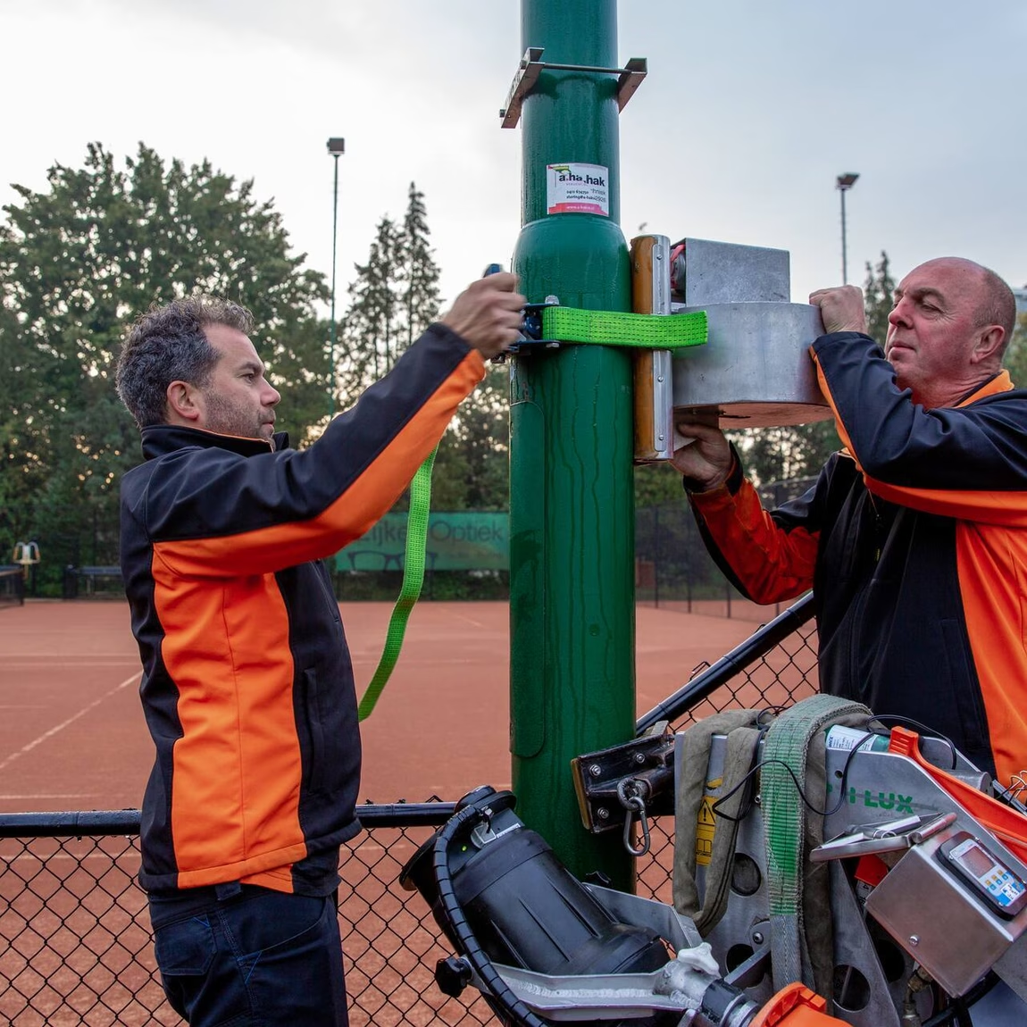
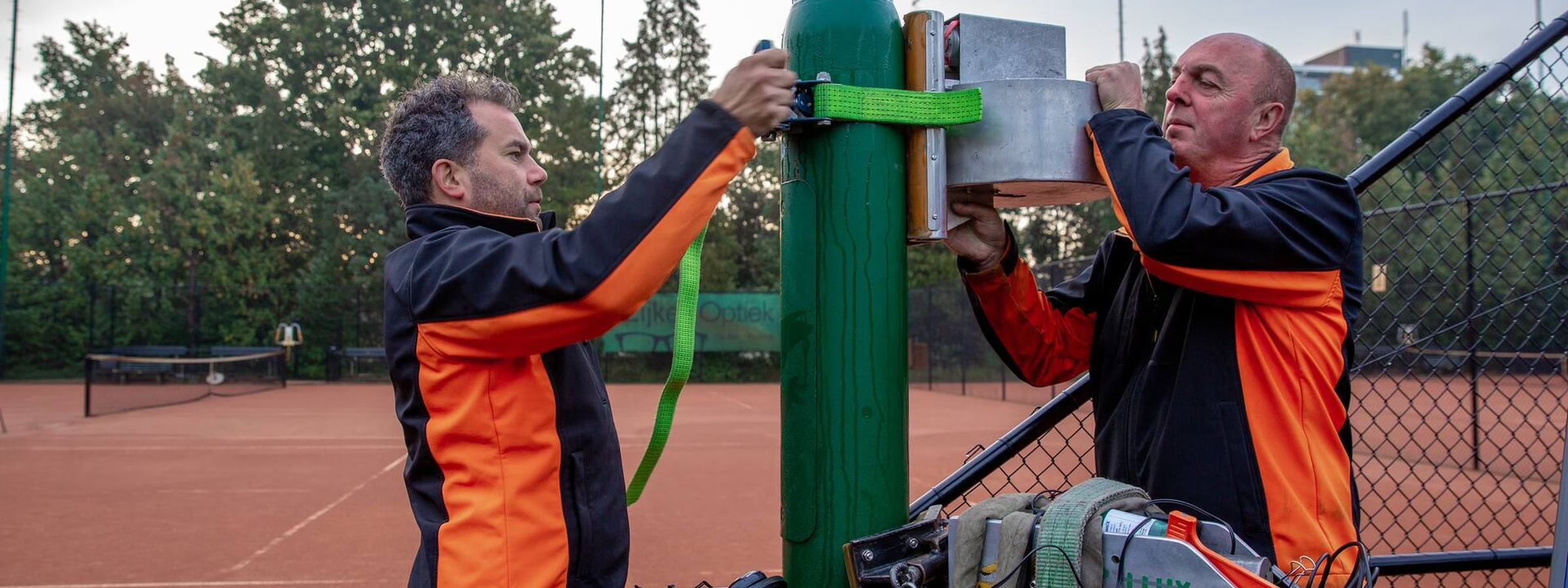
Employees are inspecting a light pole at a sports field using an aerial work platform.

Prevent Overloading of Light Poles

As an independent inspection company with more than 20 years of experience in inspecting sports field light poles, among other things, we aim to help minimize the risk of recurrence by sharing our knowledge. The subject matter is too complex and far-reaching to cover in its entirety, but with this article, we aim to use our expertise to provide insight into the basic principles and offer a few dos and don’ts. To ensure readability for those without a technical background or knowledge of LED lighting, this article has been written without using jargon as much as possible.

It is a common misconception that a light pole equipped with LED fixtures is subjected to less stress than a pole with the same number of conventional fixtures. To determine whether an existing light pole is suitable for conversion to LED fixtures, two factors are important:

  • an objective and expert assessment of the light pole’s current condition through a visual inspection and measurement; and
  • a structural analysis of the light pole (the term “strength calculation” was deliberately avoided here, as the stiffness of the pole is also a factor).

Data Required for a Calculation

To perform a reliable calculation, the following data, among other things, must be known:

The location of the light pole: the basis for calculating the wind load is the wind speed, which depends heavily on the surrounding environment.

  • The Netherlands has three distinct wind zones (NEN-EN 40-3): wind zones I, II, and III. The wind load on poles located in wind zone I is higher than that on the same pole in wind zone III. Pole manufacturers take this into account in their designs.
  • The Netherlands has four terrain categories (NEN-EN 40-3-1: 2013), namely Category I (sea or coastal area), II (unbuilt area), III (built-up areas, such as industrial zones and forests), and IV (built-up areas; city centers). In principle, wind has free rein on flat terrain, while it is calmer in built-up areas (for the sake of simplicity, we will disregard the Venturi effect here).

Pole data: available upon request from the relevant pole supplier. In the unlikely event that the pole data is unavailable, the data will need to be collected on-site. Unfortunately, it should be noted that not all data can always be obtained. Consider, for example, the type of steel used in a light pole. In the event that data is missing, it is important to assume the most plausible “worst-case” scenario. In this case, we will base our calculations on S235 structural steel.

Wind-exposed surface area of LED luminaire: depends on:

  • the brand and type of fixture;
  • the angle of the fixture relative to the horizontal plane (tilt); and
  • if multiple luminaires are installed on the pole, their positioning relative to each other is also important.

Cx value of an LED luminaire: The drag coefficient is a value that quantifies a luminaire’s aerodynamic drag. Example: A spherical luminaire, for instance, has lower aerodynamic drag than a flat plate and thus a lower Cx value. The most reliable way to determine the SCx value (the product of the projected surface area and the shape factor) is through a wind tunnel test. Ideally, the luminaire should be tested in all possible configurations in which it might be installed in practice. If no wind tunnel test has been conducted and the Cx value is therefore unknown, we use a value of 1.0 in our calculations, in accordance with NEN-EN 40-3-1: 2013. In doing so, a conservative assumption is made regarding the projected wind-exposed surface area.

Light pollution shields: It is important to note that shields placed on a luminaire to prevent light pollution often have a negative effect on the Cx value, thereby increasing the wind load. This must be taken into account in the calculation.

Weight of LED luminaire: including any driver, mounting brackets, fasteners, etc. The weight affects the strength, stiffness, and natural frequencies of a pole.

Relative position of the LED luminaire’s center of gravity: relative to the center of the light pole.

Calculation Results

The calculation results show whether a light pole complies with the standard. The most important criteria are:

  • the “Ultimate Limit State” (hereinafter: “ULS”): expresses the relative load on the pole as a number greater than 0. A value greater than 1.0 means that the load at some point in the pole exceeds the pole’s maximum load-bearing capacity and that the pole does not meet the standard.
  • the “Servicability Limit State” (hereinafter: “SLS”): the maximum permissible horizontal and vertical deflection of the pole under wind load. Three classes are distinguished (NEN-EN 40-3-3). For example, the requirements regarding the maximum permissible deflection of a tram pole or sports field pole are much stricter than those for a streetlight pole.

Pole Failure

If the ULS is greater than 1, the mast will be overloaded and will eventually fail. This will result in permanent deformation of the material or even the mast breaking at its weakest point. In principle, the weakest point of all mast types—such as conical, cylindrically tapered, octagonal, and polygonal masts—is the section around the door opening (if present). However, in the case of steel tapered cylindrical masts, a new weakest point may develop if the mast is overloaded. There are known cases where, after (prolonged) overload, a fatigue fracture occurred just above the weld seam (“heat-affected zone”) between two mast sections. In the case of fatigue, the fracture begins as a hairline crack and, under the influence of dynamic bending loads caused by the wind, will propagate from the outer surface toward the inner surface and in the circumferential direction. Eventually, the mast will fail at this location. Because the mast has already been weakened to such an extent, it is possible that it will fail even under relatively low wind loads. It is therefore important to prevent overloading at all times!

Natural Frequencies

An often-overlooked characteristic of wind-loaded masts is that they can begin to vibrate. We refer to this frequency as the natural frequency. It is a vibration frequency inherent to the structure. It is a relevant physical property of the light mast, just like its wall thickness, diameter, and height. This is caused by air vortices around the mast tube. These are easily observed on flagpoles: when there is enough wind, the flag’s fabric ripples. We call these Kármán vortices. More weight at the top of a pole results in a lower (less favorable) natural frequency.

Back to the wind: the wind can thus cause Kármán vortices to form around the mast at a certain frequency. If that frequency is close to the mast’s natural frequency, a “whipping effect” occurs: the swaying gets worse and worse, and eventually the mast will fail. It is important to determine the fundamental frequency (= lowest natural frequency) and corresponding harmonics (= multiples of the fundamental frequency) of the mast, and whether there is an unacceptable risk that the mast will be exposed to wind speeds at that natural frequency during its service life. Normally, light poles are designed so that they do not resonate under the influence of wind, and a light pole should show little to no visible movement at “normal” wind speeds. The calculations must therefore also take into account the dynamic behavior of the light pole. For low natural frequencies, the wind load is therefore multiplied by a so-called “beta factor.”

How can overloading of the pole be prevented?

Do’s:

  • Ensure you have the mast and luminaire data on hand by maintaining a management file. The reliability of the data contributes to the accuracy of the calculation.
  • Have your poles inspected periodically by an objective and knowledgeable party, such as Normec Rei-Lux B.V. Periodicinspections help minimize the risk of pole failure. In addition to inspecting the entire pole, inspecting the foundation is essential to ensure the safety and stability of the poles.
  • Be alert to severe vibrations in the pole. If a pole resonates at its natural frequency or the second harmonic, this can quickly lead to problems. In that case, contact Normec Rei-Lux B.V. as soon as possible for advice on possible next steps.
  • Always have calculations performed by a qualified party (lighting pole manufacturer or Normec Rei-Lux B.V.) when switching to LED lighting. This ensures that the lighting pole is suitable for the new load.
  • Ensure that the center of gravity of an LED fixture or LED fixtures is as close as possible to the center of the pole. This has a positive effect on the load on the pole.
  • Verify that the tilt angle matches the tilt angle used in the calculation. Deviations always affect the wind load.
  • Follow the advice of the inspection company. Independent inspection companies have no vested interest in approving or rejecting a pole. Failure to follow their advice can have serious consequences.

Don’ts:

  • Do not mount scoreboards, loudspeakers, flower boxes, or other objects on the light pole without first verifying that this does not exceed the pole’s maximum load capacity. This additional load can compromise the pole’s stability and safety.
  • Do not install light pollution shields on an LED fixture without verifying their impact through a structural analysis. The presence of light pollution shields must always be factored into the calculation.
  • Do not deviate from the parameters on which the calculation was based; if changes are made, have a new calculation performed. Consistency with the original parameters helps minimize the risk of pole failure.
  • Never drill, grind, or cut a hole in a pole without prior approval from the pole manufacturer. Holes can have a negative effect on the structural integrity and stability of a pole.
  • If necessary, preferably drill a hole in the mast hatch and/or opt for a round hole. It is important that the cut surfaces be treated with a suitable coating to prevent corrosion. Holes in the mast hatch do not adversely affect the structural integrity and stability of the mast.
  • Rectangular holes where the cuts extend into the corners are an absolute “no-go” and grounds for rejecting the light pole. High material stressescan occur in the corners, potentially leading to cracking.

Looking for an independent inspection partner?

Normec offers expert and independent inspections for safe buildings, installations, and facilities.

Contact us

Complete the form and we will contact you as soon as possible.
Naam
Privacy Policy 

Request a quote

Fill out the form and we will contact you shortly.

Naam
Privacy Policy 

Related Articles

Close-up of a green grass field showing clearly painted white lines marking the corner of a sports field. The image highlights the precise field markings and maintenance of sports facilities.
31 May 2021

Making Sports Facilities More Sustainable

Making sports facilities more sustainable has been a top priority for some time now. Sustainable investments in energy efficiency, circularity, or climate adaptation are therefore being encouraged in various ways. Examples include purchasing heat pumps, installing solar panels, or, of course, switching to LED sports field lighting. Switching to LED lighting requires a significant investment, but subsidy programs can lower that barrier. In this article, we’d like to tell you more about the options available.
Normec Rei-Lux service van parked on a city street during on-site work.
07 Mar 2023

Discussing the key points

During the Sports Facilities Trade Show on March 9, Roderik Span, Area Sales Manager at Normec Rei-lux, will discuss the key considerations when installing LED lighting on existing sports field light poles. This presentation will explain why conventional lighting cannot simply be replaced with LED lighting on sports fields. The presentation will take place in Lecture Hall A from 10:00 a.m. to 11:00 a.m.

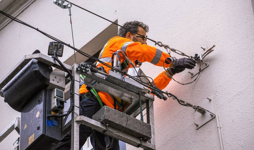
An employee inspects wall anchors and mounting points for street lighting from an aerial work platform.
20 Oct 2021

Festive Atmosphere and Coziness During the Holidays

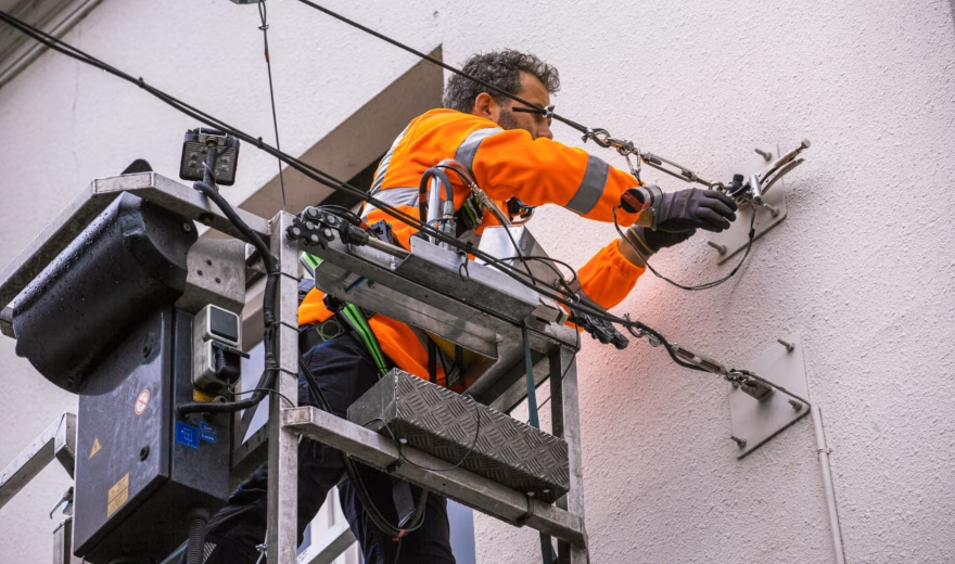
In many (usually historic) city centers, they’ve been there for decades: wall anchors. Perfect, of course, for mounting string lights. For most of the year, regular streetlights hang from the tension wires, but as the dark winter days approach, many shopping streets are transformed into a true Winter Wonderland.

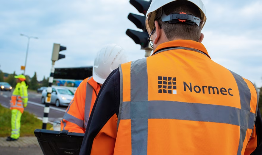
Employees are performing technical inspection work in a traffic environment.
31 May 2021

Risk Mitigation

Bridge railings, fences, and balusters contribute to public safety and are therefore essential. These structures are directly related to safety, with the goal of minimizing risks and preventing potential incidents.

A laptop is used to perform and record technical inspection work on-site.
31 May 2021

Duties of a Measurement Technician

When Ad Tijs was looking for a more challenging job 11 years ago, he first came across Rei-Lux. With training as a welder and metalworker and years of experience in engineering, he is a true metalworker through and through. A perfect fit, then, for the work at Normec Rei-Lux, and Ad joined the company in 2010.

Related Services

Static 3D Measurement

Solitaire 3D Measurement

Dynamic 3D Rotation Measurement

Dynamic 3D Measurement

Dual 3D Measurement

NEN 3140 Inspection