On the GP Prüfservice GmbH blog, our experts regularly address questions about electric motors and electrical systems and explain technical terms. Here, we focus on how to easily test overcurrent protection devices using loop impedance. And we answer the frequently asked question of whether loop impedance can be measured with a multimeter.
Contents of this article
- What Is the Purpose of Measuring Loop Impedance
- Relevant standards for determining loop impedance
- Measuring and Testing Equipment: Can I Measure Loop Impedance with a Multimeter?
- The influence of the power supply configuration according to DIN VDE 0100 on loop impedance
- How do you calculate loop impedance?
Questions about electrical testing? Get advice now!
When calculating alternating currents, impedance is the counterpart to ohmic resistance in direct current systems. You’ll encounter the term “loop impedance” particularly when designing and testing overcurrent protection devices. Here, it refers to the total AC resistance of the current loop that, in the event of an insulation fault, flows from an outer conductor through the protective conductor and the connected structure back to the outer conductor.
Have it inspected by an expert
GP Prüfservice GmbH has more than 50 years of experience with electric motors and the testing of electrical systems and equipment. Get a no-obligation consultation today.
What is the purpose of measuring loop impedance?
The practical significance of loop impedance (ZS) in connection with overcurrent protection devices lies in the fact that a certain minimum current is required to ensure sufficiently rapid activation of the circuit breaker. The short-circuit current itself is generally very difficult to determine. Measuring the loop impedance, on which it depends, is, however, simple. For example, for a circuit breaker with Class B characteristics in accordance with DIN VDE 0641 in a 230 V AC circuit with a rated current of 16 A, the loop impedance must not exceed 2.88 Ω.
Relevant Standards for Determining Loop Impedance
To determine the loop impedance, one must first consider the DIN VDE 100 series of standards, which deals with the installation of low-voltage systems up to 1,000 V AC or 1,500 V DC. Of particular interest is Group 400, “Protective Measures,” and within it, the standard DIN VDE 0100-430, “Protection of Cables and Wires Against Overcurrent.”
Further important information and definitions can be found in the DIN VDE 0413 standard, which addresses the design requirements for test equipment, such as that used for loop impedance measurement, for example, in DIN VDE 0413 Part 4, which specifies requirements for measuring instruments, and in Part 3, which addresses permissible user errors.
Guidelines for the design of standard household circuit breakers can be found in the DIN VDE 0641 standard. The DIN VDE 0660 standard, in turn, addresses switching devices and their combinations in its various parts.
The influence of the power supply configuration according to DIN VDE 0100 on loop impedance
The relevant regulations and standards permit several circuit configurations with regard to grounding. These are identified by letter combinations. The first character describes the grounding of the power source. Here, a “T” indicates a direct ground connection at a single point, while an “I” indicates that all live parts are isolated from ground potential or that only a connection via an impedance exists.
A second digit indicates the grounding of the electrical system’s structure. Here, too, a “T” indicates direct grounding at a single point, regardless of the power source’s grounding. In TN systems, however, grounding is provided via a service grounding conductor, which is in turn directly connected to earth.
An optional additional letter, which may be appended with a hyphen, is relevant for determining the loop impedance. It provides information about the use of neutral (N) and protective conductors (PE). In a TN-C system, these are combined into a PEN conductor. While you normally measure the loop impedance between the line (L) and protective conductor, separate from the neutral conductor, the second measurement point for loop impedance in such a system configuration is the PEN conductor.
Measuring and Testing Equipment: Can I measure loop impedance with a multimeter?
A frequently asked question regarding loop impedance is:
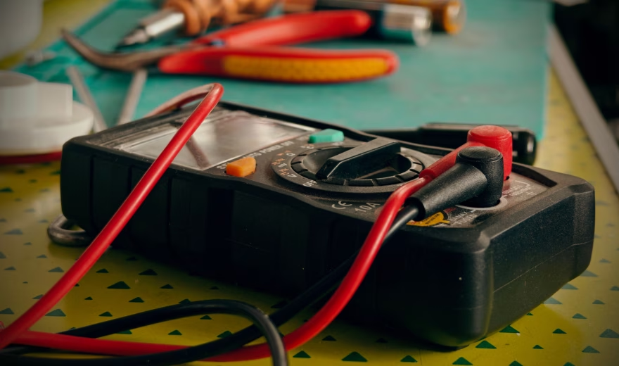
Question: Can I measure loop impedance with a multimeter?
Answer: No. Specialized test equipment is required to measure loop impedance.
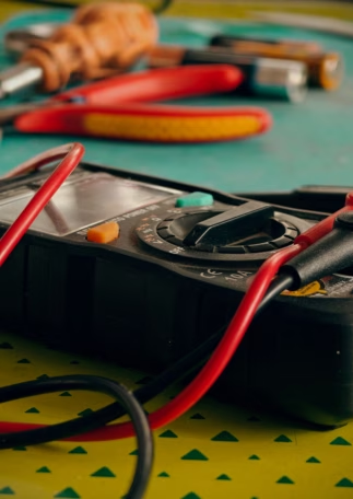
To explain why, we need to go into a bit more detail: While determining the measured quantities required to calculate loop impedance and other parameters of low-voltage equipment is, in principle, within the capabilities of commercially available multifunction testers—so-called multimeters— However, handheld multimeters—which are particularly well-suited for mobile use—often lack the necessary performance capabilities.
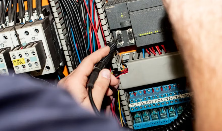
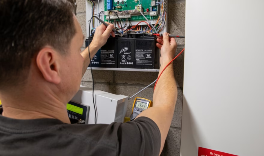
For example, digital multimeters cannot provide the current required for a correct determination of loop impedance during resistance measurement. They therefore do not meet the requirements specified in DIN VDE 0413 Part 4 and are thus unsuitable.
Requirements for Measurement and Test Equipment
The measurement voltage must be between 4 and 24 V. The measurement currents must be at least 0.2 A for direct current or at least 5 A for alternating current.
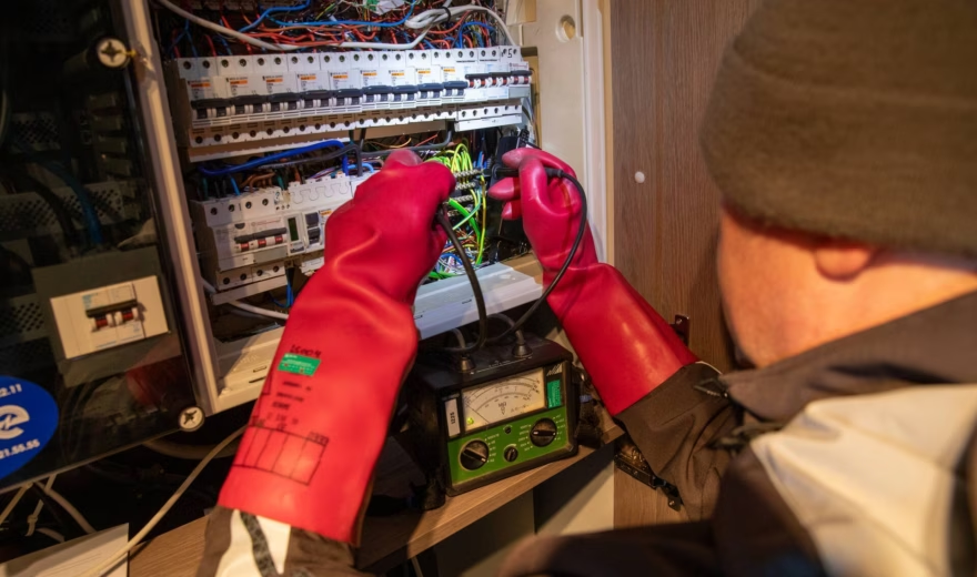
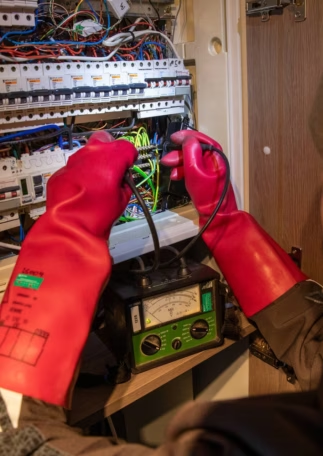
For loop impedance measurement and other installation tests, special test equipment is therefore generally required; this equipment is marketed as loop resistance testers. Such installation testers usually offer the additional advantage of supporting the creation of the required test reports, for example, through appropriate data storage capabilities. Since loop resistance testers are quite expensive compared to a multimeter, outsourcing the necessary tests is usually the better solution, especially for smaller companies. GP Prüfservice GmbH would be happy to provide you with a quote.
How is loop impedance calculated?
Now that we’ve covered the meaning, regulations, and requirements for measuring instruments, the question remains: how is loop impedance actually calculated? You can determine the loop impedance ZS from the measurement voltage and the measurement current between a phase conductor and the protective conductor, or the PEN conductor in a TN-C system. The calculation is performed using the equation ZS = U0 / Ia, where U0 denotes the rated voltage (since 1987, 230 V single-phase / 400 V three-phase) and Ia denotes the trip current.
For circuit breakers with characteristic B according to DIN VDE 0641, Ia should be set to five times the rated current IN of the protective device; for circuit breakers with characteristic C, it should be set to ten times the rated current. This results, for example, in maximum permissible values for the loop impedance of circuit breakers with characteristic B in a 230 V system of:
- 7.3 Ω at IN = 6 A
- 4.6 Ω at IN = 10 A
- 2.88 Ω at IN = 16 A
- 2.3 Ω at IN = 20 A
- 1.84 Ω at IN = 25 A
- 1.44 Ω at IN = 32 A
According to the version updated in 2007, when determining the loop impedance, the increase resulting from the heating of the conductors in the event of a fault must also be taken into account. For this reason, the initially determined value of the loop impedance must be corrected by a factor of 2/3. The example table then looks as follows:
- 4.87 Ω at IN = 6 A
- 3.07 Ω at IN = 10 A
- 1.92 Ω at IN = 16 A
- 1.53 Ω at IN = 20 A
- 1.23 Ω at IN = 25 A
- 0.96 Ω at IN = 32 A
In addition, further corrections for measurement errors in the test equipment must be taken into account, which, according to DIN VDE 0413 Part 3, are set at 30%. The actual current may therefore deviate from the measured value by between -23% and +43%.
What should be considered when testing loop impedance?
In addition to the impedances of the outer conductor and the protective conductor (or PEN conductor), the loop impedance also includes the AC resistance of the current source. The accuracy of the loop impedance measurement depends on the stability of the voltage during the measurement process. For trip times, which—in accordance with the standard—may be 0.2, 0.4, or 5 seconds depending on the characteristics of the respective circuit, it is recommended to verify the measurement results by taking multiple measurements.
If the required loop impedance values are not achieved during the inspection of the electrical installation, you can ensure the effectiveness of the protective device by taking the following measures, among others.
- Installing a new conductor with a larger cross-section.
- Installing an additional residual-current circuit breaker (RCCB). The overcurrent protection device then serves only to protect the circuit. Dangerous body currents, on the other hand, are interrupted early by the RCCB.
We’d be happy to advise you!
GP Prüfservice GmbH in Dortmund is your expert for DGUV V3 inspections. Our team has more than 50 years of experience with electric motors and industrial services. We handle the inspection of electrical systems and equipment for you in North Rhine-Westphalia and nationwide.